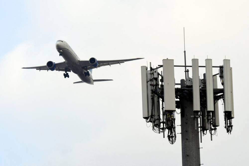
The 5G interference with aircraft systems has been the talk of the town for the past few months. One of the major systems that are affected by 5G emissions is the radio altimeter. This piece of equipment has been in aircraft operations for the past 50 years, and it has been very successful. One of the main functions of the radio altimeter is to show the altitude of the aircraft, but this is just one small function of it. It is connected to many other critical aircraft systems. Consequently, an erroneous radio altimeter can be a major safety issue.
The working principle of a Radio altimeter
The radio altimeter uses the radar principle. In a typical radio altimeter setup, there are two antennae. One sends a signal and the other receives it. The signal is sent by the transmitter antenna. This signal then gets reflected by the ground or the surrounding terrain and is then received by the receiver antenna. As the signals travel at the speed of light, the distance can be calculated by simply measuring the time it takes for the reflected signal to be received by the aircraft.
The radio altimeter operates at a frequency of 4.2-4.4 GHz and for a long time, this band has been protected to reduce harmful radio interference. When mobile telecommunications boomed in the 21st century, it did not initially become a risk for the radio altimeters as the communications operating frequencies were well below the radio altimeter operational frequency.
However, with the introduction of 5G technology, the telecommunication frequency has closed to that of the radio altimeter frequency. With the 5G, the frequency band is between 3.7-3.98GHz, well close to that of the radio altimeter frequency. This can cause interference in the radio altimeter which can lead to erroneous altitude measurements.

Incorrect radio altimeter readouts can have a multitude of effects on various aircraft systems, with some of these systems directly affecting the safety of the aircraft. These systems include the Traffic Collision Avoidance System (TCAS), the Ground Proximity Warning System (GPWS), the Predictive Windshear System (PWS), the Auto flight system, and the Fly by wire and other control systems.
Traffic Collision Avoidance System (TCAS)
Traffic Collision Avoidance System (TCAS) is used by aircraft to prevent collisions with other aircraft. The system uses the closure rate between aircraft to generate avoidance guidance for the pilot to follow if two aircraft are on a collision course. This guidance called Resolution Advisories (RA) gives descent or ascent orders for pilots to follow.
These maneuvers can sometimes be quite violent and can pose a crash risk close to the ground. Hence, some TCAS alerts are inhibited when the aircraft is at low altitudes. The altitude for this is determined by the radio altimeter. In most aircraft, when below 1000 ft all RA messages are inhibited when the aircraft is in a climb and all RA messages below 900 ft are inhibited when in a descent.
A false radio altimeter height can make the TCAS give out false resolution advisories when the aircraft is near the ground which can lead to Controlled Flight Into Terrain (CFIT).
.JPG?q=50&fit=crop&w=1500&dpr=1.5)
Ground Proximity Warning System (GPWS)
The GPWS uses the radio altimeter to calculate how close the aircraft is to the terrain or ground. This system also uses the change in radio altimeter height to determine raising terrain and give out timely cautions and warnings to the pilot of an impending terrain impact.
The GPWS can give out aural alerts such as “TERRAIN, TERRAIN”, “PULL UP”, “DON’T SINK, DON’T SINK” etc. to grab the attention of the pilot so that he/she can immediately apply the avoidance maneuvers. As the GPWS depends on the radio altimeter to generate such alerts an invalid radio altimeter can feed wrong data into the GPWS system which can prevent it from alerting the pilots leading to a terrain impact.

Predictive Windshear System (PWS)
The PWS is used to detect areas of windshear when the aircraft is close to the ground (takeoffs and landings). The radio altimeter feeds altitude data into the PWS system so that it does not activate when the aircraft is at high altitudes. Typically, the PWS operates, when the aircraft altitude is below about 2000 ft. If the radio height is not correctly fed to the PWS system, it may fail to show windshear to the pilots. This can extremely dangerous when taking off and landing where the aircraft is at a low speed and not in a situation to deal with strong vertical gusts caused by windshear.

Auto flight system
The aircraft auto flight system uses the radio height when close to the ground for various purposes especially when conducting auto-coupled approaches in low visibility conditions, where the aircraft systems automatically land the aircraft. During such operations, the auto flight system functions heavily rely on the radio altimeter height.
For example, the timing of the flare for landing is decided by the radio altimeter height. If for example, an aircraft flare is set at 30 ft and if the radio altimeter height becomes erroneous and gives the auto flight a higher altitude, the aircraft may not flare. This can lead to a hard landing which can severely damage the aircraft, and injure passengers and crew.
The engine thrust during an automatic landing is also controlled by the radio altimeter height, whereby it is reduced at a particular height. For instance, if the autothrottle/autothrust system is designed to pull the engine power to idle for landing at 25 ft and if a faulty radio altimeter makes the aircraft think that it is 25 ft when it is way up, the thrust may go to idle. When close to the ground this can lead to a disaster as jet engines take about 7-8 seconds to spool up from idle to maximum thrust. So, even if the pilot applies full thrust in such a situation, it might not be enough to save the day.

Fly-by-wire and other control systems
Most modern aircraft today have fly-by-wire control systems. In a fly-by-wire control system, the pilot inputs are sent to a computer which then manipulates the control surfaces based on a programmed set of laws. One example is pitch control in an Airbus aircraft. When the pilot gives a side stick demand, it is converted to a G-load demand and then the computers deflect the required control surfaces and trim the stabilizer out to give the pilot the desired pitch demand. If the pilot gives a +1.5 G demand on the stick, the aircraft is pitched up to that G-load and when the stick is released, the aircraft maintains a 1 G trimmed flight in a constant climb.
The control laws differ when the aircraft is in the air and when on the ground. Again, an example can be derived from an Airbus fly-by-wire aircraft. Because the aircraft maintains a 1 G flight with the side stick released by the pilot, it maintains a constant flight path as such. This can be quite unnatural when the pilot tries to land the aircraft.
In a landing, the pilot uses his peripheral vision to see the aircraft sinking to the runway and carefully modulates his/her control inputs to touch down at an acceptable sink rate. This is called the landing flare. In the Airbus fly-by-wire, at 50 ft (100 ft for larger Airbuses), a flare law is introduced. The height for this law conversion comes from the radio altimeter.
The flare law effectively gives the pilot direct control over the pitch controls (the elevator) and cancels the auto trim. This makes the aircraft behave like a conventional aircraft and a constant back input on the side stick is required to keep the aircraft from hitting the ground in a nose-down attitude. If the radio altimeter is erroneous, the aircraft may go into flare law early making the aircraft difficult to control, especially in a go-around as additional force on the side stick is required to control the aircraft.
In some aircraft, such as in the Boeing 787 models, the control systems rely heavily on the radio altimeter data. The FAA found that an anomalous radio altimeter can have the following effects on the 787 systems:
- Autothrottle may remain in speed (SPD) mode and may increase thrust to maintain speed during flare instead of reducing the thrust to IDLE at 25 feet radio altitude (RA) or may reduce thrust to IDLE prematurely.
- Thrust reversers may not deploy above 65 knots during the landing roll.
- Engines may remain at approach idle after touchdown until 65 knots during the landing roll.
- Auto Speed brake may be inoperative during the landing roll.
- SPEEDBRAKE EXTENDED Caution message may not be available during the landing roll.
- SPEEDBRAKE time-critical visual and aural warnings may not be available during the landing roll.
- Spoilers may be limited to their maximum in-flight position during manual deployment after touchdown until 65 knots during the landing roll.
- Other simultaneous flight deck effects associated with the 5G C-Band interference could increase pilot workload.
The failure of systems above to work correctly can result in an increased landing distance which puts the aircraft at the risk of a runway excursion, especially on a runway with a reduced friction coefficient caused by rain or snow. Due to these findings, the FAA released an Airworthiness Directive (AD) which called for operators to bring changes to the Aircraft Flight Manual (AFM).
These changes included the prohibition of aircraft dispatch with certain equipment inoperative, such as Anti-skid. It also prohibits dispatching of the aircraft when destination runway conditions are below a certain braking coefficient. The AFM edit also contains estimated landing distances for an aircraft landing in a possible 5G interference. Even though the 787 is the most affected aircraft, ADs have been issued to 747-8, 777, 767, and 757 which slightly affects the content of the AFM.

For Airbus aircraft, so far there have been no ADs issued. However, the manufacturer has several times released Flight Operations Transmissions (FOTs) to their customers as a guidance on the work and research they have been doing regarding the issue. The Airbus aircraft radio altimeters also suffer from interference and can cause issues to the discussed systems above. However, Airbus is adamant that such interference does not affect systems that are critical in stopping the aircraft once on the ground such as the activation of the spoilers and reverse thrust as their design uses multiple redundant logic and systems to confirm that the aircraft is on the ground and make that transition from Air to the Ground.