Summary
- Fuel is stored in various tanks within the aircraft to prevent wing bending stresses and control the center of gravity.
- The fuel is pumped from the tanks to the engine through tank pumps, and suction valves allow fuel to be drawn in case of pump failure.
- Fuel is also used for other functions such as running actuators and cooling electrical generators.
The fuel system is one of the most critical systems of any aircraft. From storage, channeling, and distribution, to its pressure and temperature, the fuel runs through various sub-systems and components before being used for combustion. The fuel stored on the aircraft must be channeled precisely and efficiently to engines and supporting systems.
A variety of gauges, transmitters, and sensors are installed within the fuel system to achieve fuel readings throughout the system. This article delves deeper into the aircraft fuel system, its components, and functionalities, as highlighted by the Aircraft Owners and Pilots Association Blog.
The fuel storage tanks and venting system
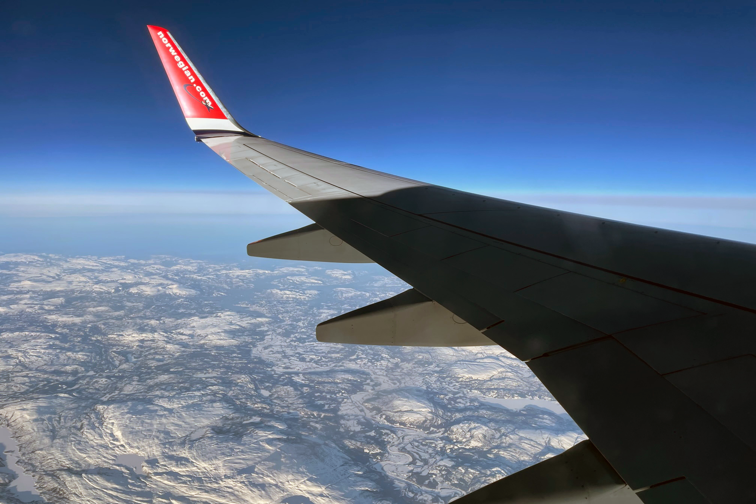
In most large aircraft, the fuel is stored in the wings, although some aircraft also have tanks in the center body, or the center fuselage, called center tanks. Additionally, widebody aircraft have extra tanks in the tail or the horizontal stabilizer, which are used to control the center of gravity of the aircraft during long-haul flights.
The storage of fuel in the wings helps to prevent wing bending stresses. Due to this reason, wing tank fuel is used last during the course of the flight. For example, if an aircraft has a center tank, the center tank fuel is used first before the fuel is drained from the wings.
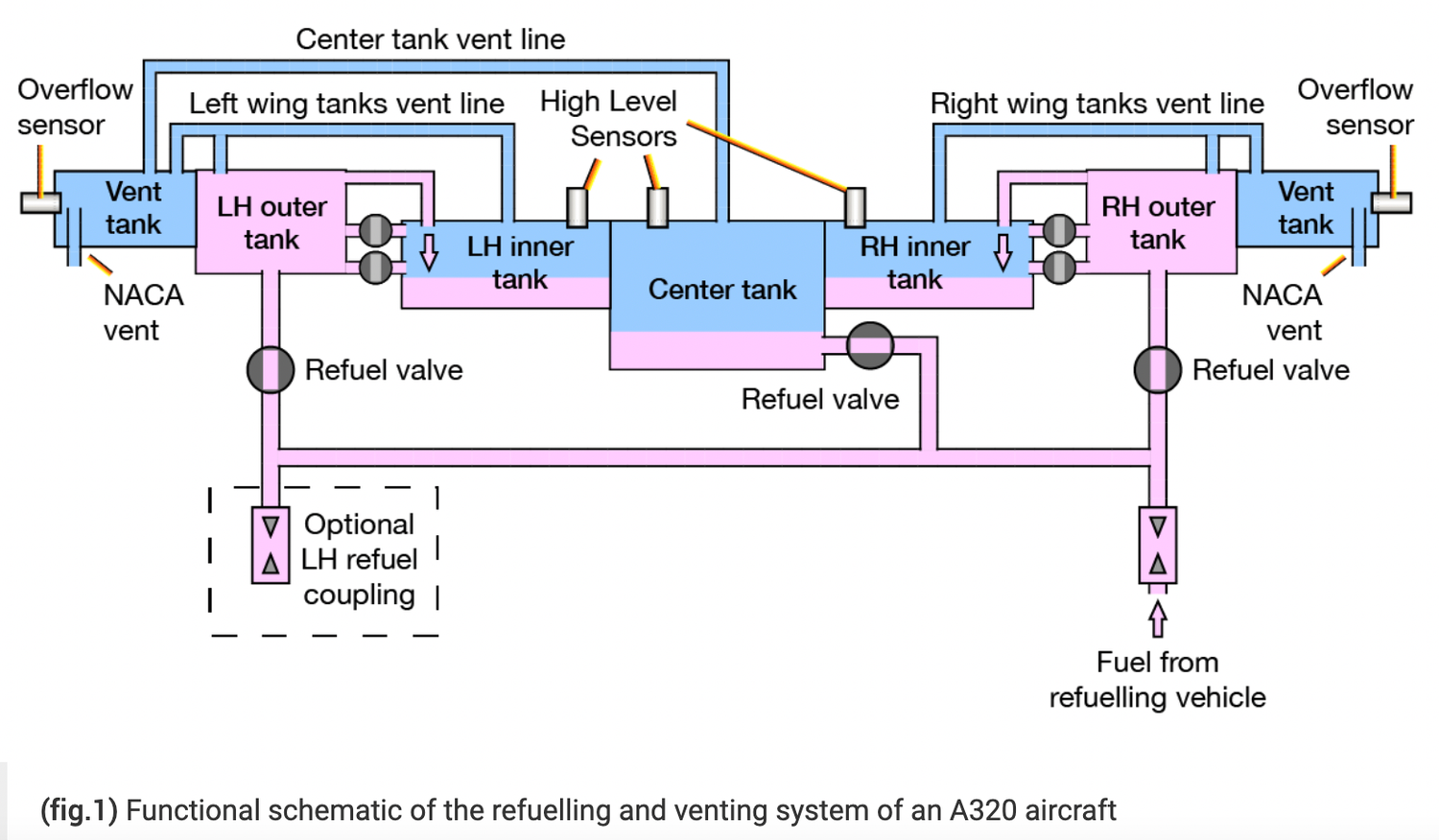
Also, in larger aircraft, the wing tank is divided into an outer and inner tank. In this case, the inner tank fuel is used before the fuel from the outer tank is used. This again helps to relieve stresses on the wing.
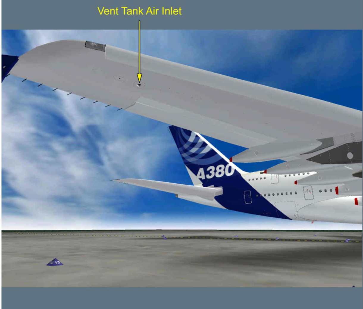
In addition to the storage tanks, there are tanks present in the fuel system known as surge tanks, which are also a part of the fuel vent system. All the main fuel tanks in the aircraft are connected to the surge tank through a vent pipe.
During aircraft maneuvering, any fuel that moves out of the tanks falls into the surge tank through the vent pipe. Subsequently, when the aircraft levels off, the fuel from the surge tank is gravity-fed back to the main tanks.
The surge tank is also vented to the atmosphere to release fuel if there is a fuel overflow. It is, at the same time, provided with ram air which helps to pressurize the main fuel tanks, which keeps the tanks at a slight positive pressure.
This prevents excessive evaporation. As the aircraft climbs higher and higher, the reduced atmospheric pressure decreases the boiling point of the fuel, which causes it to evaporate. When the tanks are fed with positive pressure, the fuel is kept from experiencing reduced pressure. The positive pressure also helps to prevent a vacuum from developing in the tanks as the engines draw fuel from the tanks.
The inner workings of the fuel system
The fuel tanks consist of tank pumps or fuel booster pumps which can be controlled by the pilot. In most cases, each tank has two pumps, which are powered by the main electrical system of the aircraft. The job of these pumps is to pump the fuel from the fuel tanks to the main engine-driven fuel pump, which then pumps fuel to the engine itself.
In aircraft capable of flying at high altitudes, the tank pumps are a necessity because the reduced pressure at altitudes can cause fuel to boil, causing vapor locks that can prevent fuel from entering the engine-driven pump.
The fuel tank also consists of suction valves that allow fuel to be drawn by the engines in the event of tank pump failure. This requires the pilots to descend to a lower altitude, which prevents low-pressure fuel boiling.
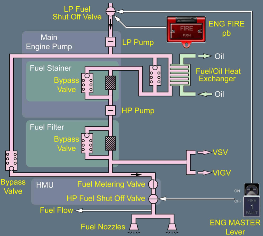
Once the fuel is pumped by the tank pumps, it is then routed to the low-pressure (LP) fuel valve, sometimes called the spar valve. From there, the fuel passes through the engine-driven pumps. Some aircraft have both a low-pressure pump and a high-pressure pump, driven by the high-pressure compressor of the engine.

What Happens To Fuel Dumped By Aircraft?
Aircraft sometimes have to dump fuel, but what actually occurs during the process?Before the fuel is routed to the main engine components, it goes through the fuel/oil heat exchanger and the fuel filter. The heat exchanger keeps the fuel at an optimum temperature, while the filter blocks any debris in the fuel. Once passed through the exchanger and the filter, the fuel is pumped by the high-pressure pump to the fuel nozzles in the combustion chamber.
The fuel is also used to run the actuators of systems such as the variable stator vanes inside the engines using fuel hydraulic signals. In some aircraft, the fuel is also used to cool the electrical generators.
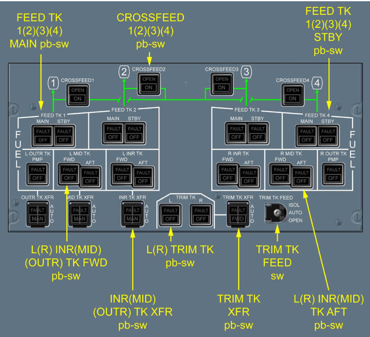
In normal operations, the left-wing tank supplies fuel to the left engine, and the right-wing tank supplies fuel to the right engine. In an engine flameout event, the remaining engine can be supplied with fuel from the other side using a crossfeed valve. For example, if the right engine were to fail, fuel from the left-wing tank could be routed to the right engine when the crossfeed valve is opened.
The crossfeed can also be used to balance the fuel in the air between the tanks. To perform this procedure, the pilots can turn off the wing tank pumps of the lighter side and open the crossfeed valve. This allows the fuller tank to supply both engines. Once the balance between the tanks is achieved, the wing tank pumps can be turned back on and the crossfeed valve can be closed.
.jpeg?q=50&fit=crop&w=1500&dpr=1.5)
The fuel for the Auxiliary Power Unit (APU) is typically fed from one of the wing tanks. It has a pump of its own which automatically comes on when the APU start sequence is initiated. If the APU pump were to malfunction, the supplying tank pumps could be turned on.
Refueling procedures
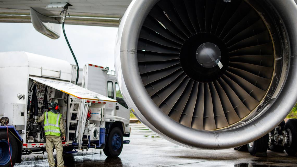
The refueling points in most large aircraft can be found under the wings, although, in some aircraft, it is in the side belly. This point is called a refuel coupling, and it is where the fuel bowser hose is connected. This type of fueling is known as pressure fueling, as the fuel is delivered to the tanks at a high pressure.
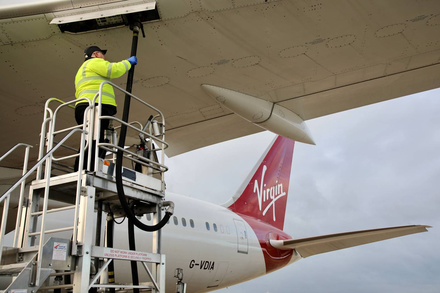
To control the refueling, a control panel is available. In this panel, the operator can dial in or pre-set the amount of fuel that is required. Once the hose is connected, the refueling valves open, and the fueling begins, with this entire process being automatic.
During refueling, the outer tanks are filled up first, and, once they are full, fuel overflows into the inner tank and the center tank. When the fuel level reaches the selected value, the refueling valves are closed, and the fueling stops.

Most manufacturers also provide a means to fuel the aircraft manually using gravity. For this, manual refueling points are located on the wings. In manual refueling, the fueler controls the refueling, and it is recommended to fill up the wing tanks before filling up the center tanks. The main disadvantage of this type of refueling is that it can take a lot of time to complete the fueling process.
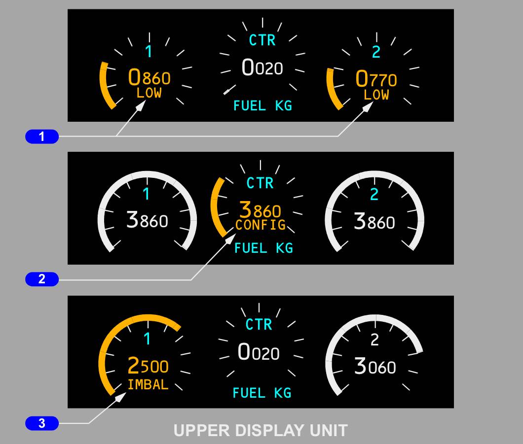
How is fuel quantity measured?
To measure the fuel quantity, capacitors are used. The capacitor consists of two plates that are supplied with AC electrical current.
The current flow in such a circuit depends on four factors. They are:
- The level of voltage applied.
- The frequency of the supply.
- The size of the capacitor plates.
- The dielectric constant.
The first three of these factors (voltage, frequency, and plate size) remain fixed, and the only factor that changes is the dielectric constant. This is because, at a given time, the dielectric constant can either be air, fuel, or a mixture of air and fuel.
As the capacitor is drenched in fuel, there is an increase in current, which is compared to a reference capacitor with air as a dielectric. The difference in these two measurements can then be used to get a very accurate indication of fuel.

The main problem with this system is that it cannot compensate for the temperature. The Specific Gravity (SG) or density of the fuel is inversely proportional to the temperature, meaning that, when there is a drop in temperature, the fuel volume reduces and causes errors in fuel indication. Similarly, when there is an increase in the temperature, fuel volume increases.
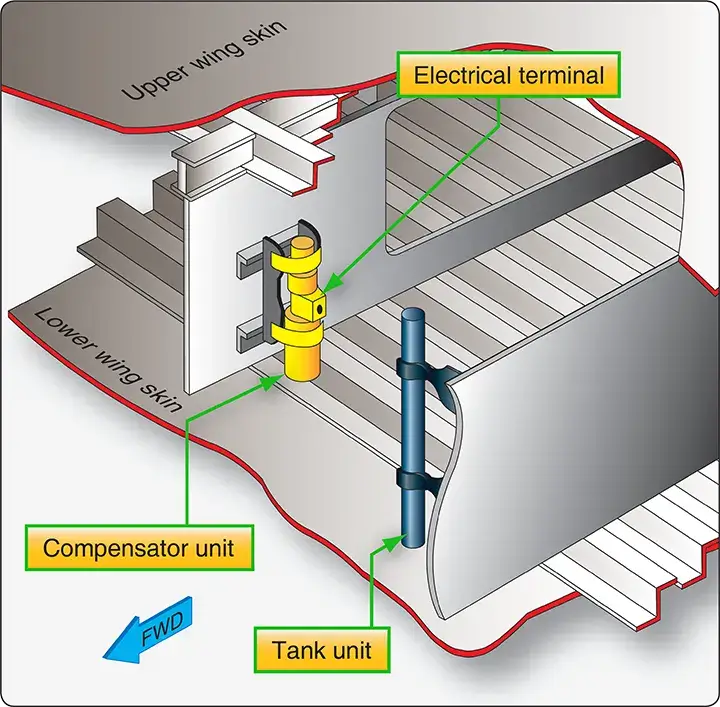
To solve this problem, compensators are used. These are probes that are placed deep inside the fuel tanks to ensure that they are always covered in fuel. If there is a reduction in temperature that causes the SG to go up, the compensator increases the current flow to the fuel indicator circuit to correct the erroneous measurement by the fuel-measuring capacitors.
What are your thoughts on the aircraft fuel system, components, and functionalities? Share your views in the comments section.