What do you understand when it comes to aircraft take-off performance? A takeoff for a layman might be the point the aircraft lifts off the runway. However, a takeoff involves a lot more. In this write-up we will dive deep into the takeoff performance of a large aircraft.
Takeoff Distances Available
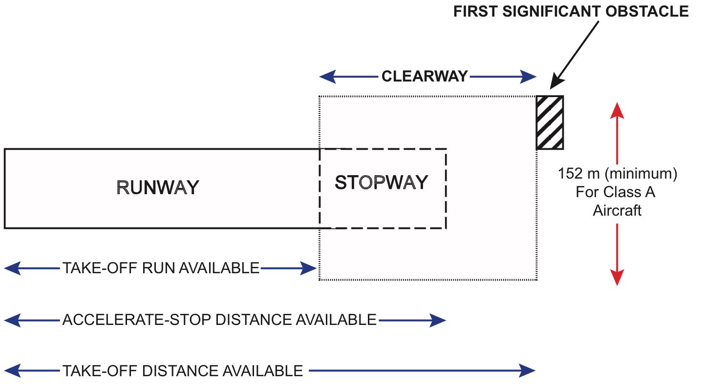
The first takeoff distance available is the Takeoff Run Available (TORA). This is the distance from which an aircraft can begin its takeoff roll to the point, where the surface can no longer bear the weight of the aircraft.
The second is the Takeoff Distance Available (TODA). This is TORA plus the clearway (if the runway has one). A clearway is an area beyond the runway surface where no terrain or no object that can hit the aircraft is present. Typically, a clearway is about 152 m wide and must not have a slope greater than 1.25%. If the runway has no clearway, then TODA is equal to the TORA.
The last is the Accelerate-Stop Distance Available (ASDA). This is the distance available to stop the aircraft in an event of a rejected takeoff. The ASDA is equal to TORA plus the stopway, if available. Stopways are designed to stop an aircraft during an aborted takeoff. They are usually not as strong as the runway surface. A stopway most of the time cannot handle a heavy speeding aircraft. If a stopway is not available, then ASDA equals TORA.
Takeoff Speeds
There are several speeds involved in a takeoff. The important thing to remember at this point is that all takeoff performances in aircraft are calculated with a failed engine (the worst-case situation, as far as aircraft performance is considered). Now, let us discuss the various speeds in more detail.
Minimum Control Speed on the Ground, VMCG
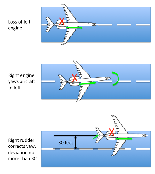
The VMCG is the minimum speed at which the aircraft can be controlled using rudder controls with the critical engine made inoperative. As the rudder is an airfoil, it requires airflow to make it effective. The higher the speed of the aircraft, the higher the aerodynamic forces and the more effective the rudder controls. During the VMCG demonstration, the aircraft must be able to counter the undesirable yaw of an engine failure with a less than 30 ft excursion from the runway center line.
Minimum Control Speed in the Air, VMCA
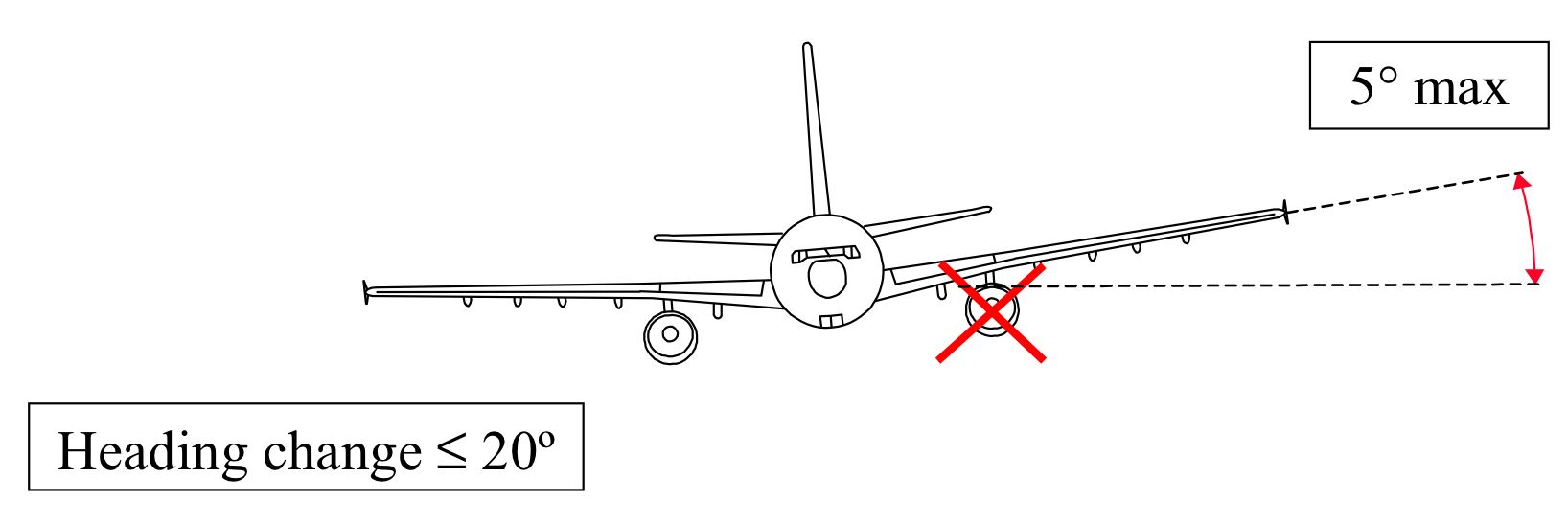
VMCA is the minimum control speed in the air with the critical engine inoperative. Below VMCA the aircraft cannot be controlled with the flight controls. VMCA is determined by showing that the aircraft can maintain straight and level flight with the rudder and a maximum bank angle of 5 degrees applied towards the live engine.
Minimum Unstick Speed, VMU
VMU is the lowest speed at which an airplane can safely lift off the ground and continue the takeoff.
During the VMU demonstration, the pilot pulls back on the controls of the aircraft at a very low speed giving the aircraft a slow rotation. In a geometrically limited aircraft, this causes the tail of the aircraft to scrape on the runway. This tail strike limits further increase of angle of attack and prevents a stall close to the ground allowing these aircraft to have lower takeoff speeds and better performance.
Engine Failure Speed, VEF
This is a design speed. It is determined by the aircraft manufacturer during the certification phase of the aircraft. This is purely a design speed and not an operational speed.
Decision Speed, V1
This is the maximum speed at which the pilot must decide to reject the takeoff. This speed ensures that the takeoff is rejected safely within the remaining runway. As per regulations, V1 should not be less than VEF plus any speed gained with the critical engine failure and the point where the pilot recognizes and reacts to the engine failure. Research has shown that it takes a pilot 1 second to react to an engine failure situation. Thus, the V1 should occur at least 1 second after reaching VEF. It can never be less than 1 second.
Rotation Speed, VR
The VR is the speed at which the pilot must initiate the rotation for the lift-off by pulling back on the controls. It may not be less than:
- V1
- 1.05 VMCA
- The speed that allows reaching takeoff safety speed, V2 before reaching 35 ft screen height.
Lift-off Speed, VLOF
VLOF is the speed at which the aircraft first becomes airborne. The VLOF must not be less than 1.10 VMU in all engine operating conditions and not less than 1.05 VMU with a critical engine made inoperative.
In geometrically limited aircraft, the margin is reduced to 1.08 VMU with all engines operative and 1.04 VMU with an engine inoperative. Most commercial airliners are geometrically limited. That is, during VMU demonstration, they hit the tail which limits the maximum angle of attack reached.
Takeoff Safety Speed, V2
V2 is the minimum speed to be maintained at a height of 35 ft above the runway, with an engine inoperative. It is called safety speed because with this speed the aircraft can maintain the minimum regulatory climb gradient with a failed engine. V2 must not be less than V2min, a speed which must not be less than 1.13 VSR (stall reference speed) and 1.10 VMCA.
In all, the V2 should always be higher than V2min and VR plus speed gained before reaching a screen height of 35 ft.
Maximum Brake Energy Speed, VMBE
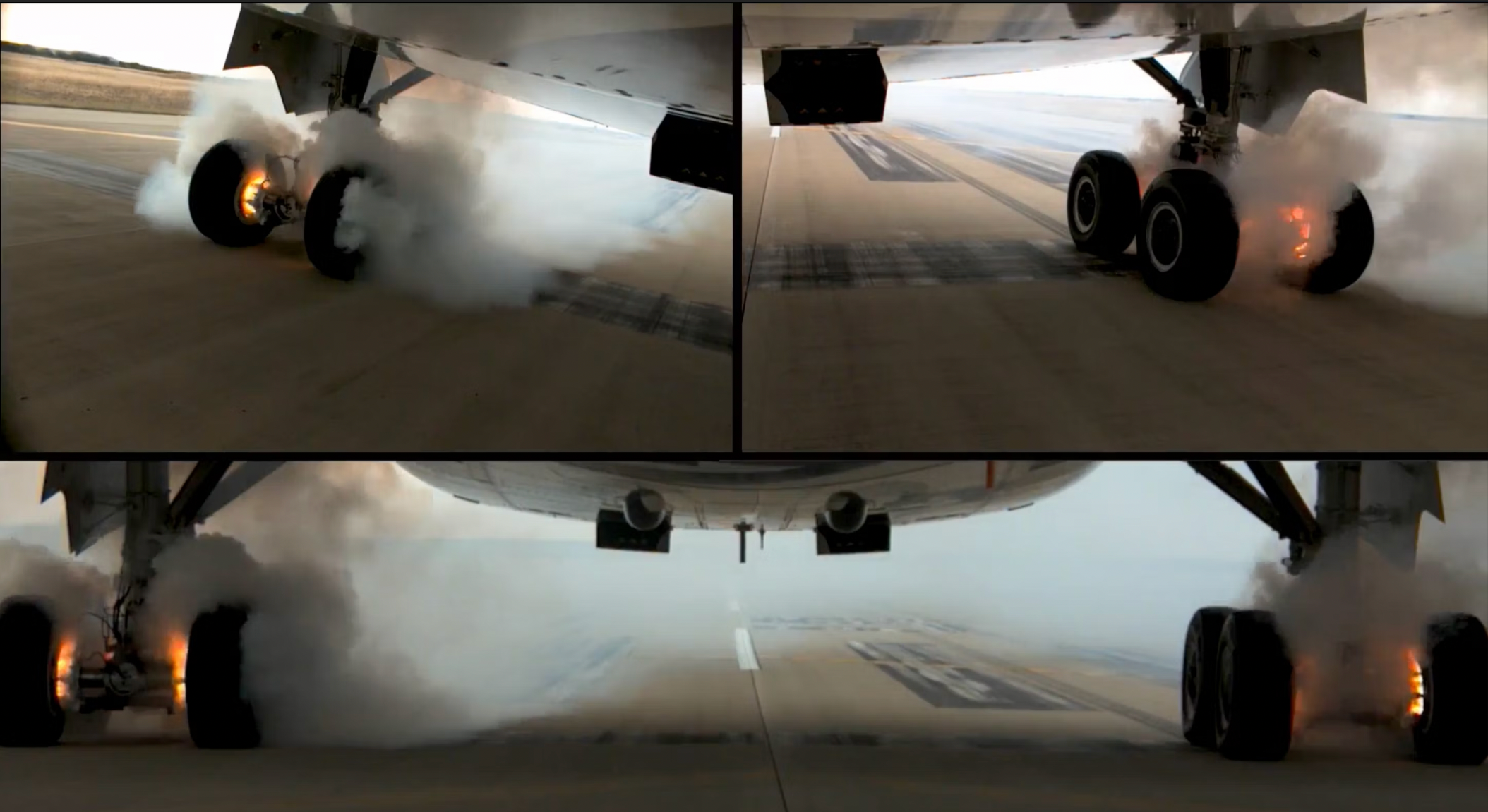
During a takeoff, a rejected takeoff is a highly likely event. In a rejected takeoff, sometimes a large amount of kinetic energy needs to be dissipated. At or above VMBE, the brakes can no longer contain the energy dissipation and heats up, and can even catch on fire.
Takeoff Distance Required and Accelerate-Stop Distance Required
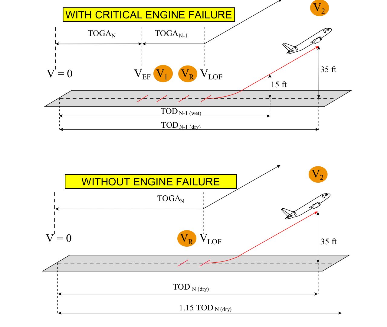
The Takeoff Distance for a dry runway (TOD DRY) is the highest of TODN-1 DRY and 1.15 TODN DRY. The TODN-1 DRY is the distance covered from brake release to the point at which the aircraft reaches a screen height of 35 ft with critical engine failure. The 1.15 TODN DRY is 115% of the distance covered from brake release to a screen height of 35 ft with all engines operative. It can be simplified as follows:
TOD DRY = Max of (TODN-1 DRY; 1.15 TODN DRY)
When the runway is wet, TOD WET is the highest of TOD DRY or the TODN-1 WET, where the latter is the distance covered from brake release to a point where the aircraft reaches a screen height of 15 ft, ensuring V2 speed is reached at least by 35 ft with the critical engine inoperative. This can also be simplified as:
TOD WET = Max of (TOD DRY; 1.15 TODN-1 WET)
For a twin-engine aircraft, TOD with engine failure is always the highest, because of the greatly reduced performance. However, for a four-engine aircraft, the limit with an engine failed is TOD multiplied by 1.15 because an engine failure has very little effect on its actual performance because it still has three live engines.
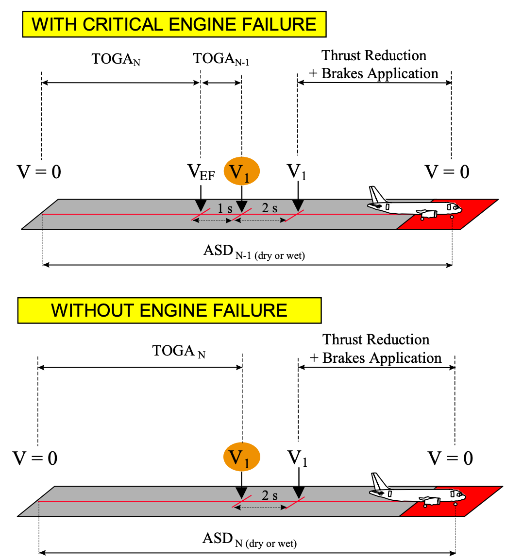
The Accelerate-Stop Distance Required on a dry runway (ASD DRY) is the highest of ASDN-1 DRY and the ASDN DRY.
The ASDN-1 DRY is the total distance necessary to accelerate an aircraft with all engines operative to VEF, then accelerate to V1 with the critical engine failed and the distance that is covered during which the pilot takes action to stop the aircraft to the point it comes to a stop. It also includes 2 seconds reaction time from V1 before the pilot applies braking and thrust reduction on the remaining engine.
The ASDN DRY is the total distance necessary to accelerate an aircraft with all engines operative to V1, at which point the pilot takes action to stop the aircraft to the point it comes to a stop. It also includes 2 seconds reaction time from V1 before the pilot applies braking and thrust reduction on the engines. The ASD DRY can be simplified as:
ASD DRY = Max of (ASDN-1 DRY; ASDN DRY)
The definitions for ASD on a wet (ASD WET) runway is the same as for ASD DRY except that the runway is wet. Thus, it can be simplified as follows:
ASD WET = Max of (ASD DRY; ASDN-1 WET; ASDN WET)
The concept of V1 Speed
The V1 is one of the most interesting speeds in a takeoff in that it can be varied while respecting some limits. The V1 should not be greater than or lower than some speeds mentioned earlier. This is shown below:
VMCG ≤ VEF ≤ V1 ≤ VMBE ≤ VR
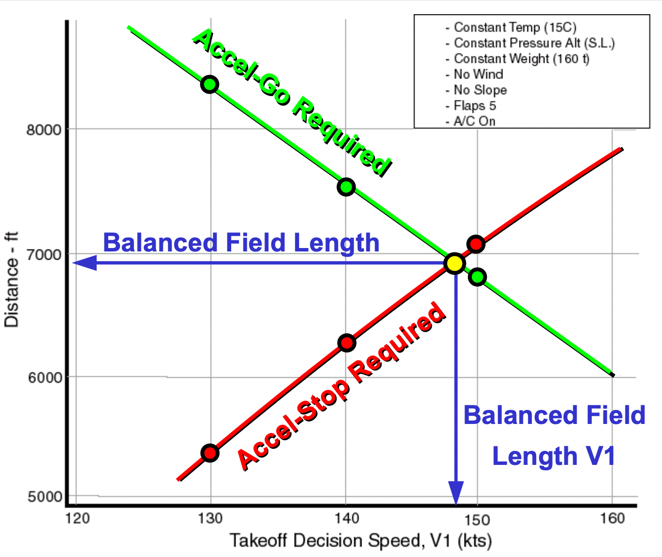
To see how the V1 is varied, the easiest is to use a graph. The graph below shows Runway Distance (ft) on the y-axis and Decision speed V1 on the x-axis. Two lines are plotted on the graph. The green line is the TODN-1 or the Accel-Go Required. The red line is the ASDN-1 or the Accel-Stop Required. As the V1 speed is increased, the TODN-1 decreases, and at the same time, the ASDN-1 increases with speed.
As explained previously TODN-1 and ASDN-1 are distances the aircraft covers with one engine inoperative. In the case of TODN-1, the higher the V1, the later it is considered that the engine fails in the takeoff. This means that the aircraft can accelerate with two engines operative for most of the part of the takeoff run. More acceleration means more lift and the faster can the aircraft lift off the runway, reducing the TODN-1.
The ASDN-1 concerns stopping the aircraft. So, the later the engine fails on takeoff, the more time the aircraft spends accelerating with two engines and the more speed and thus the more kinetic energy it gains before the engine failure. More kinetic energy means more runway distance is required to stop the aircraft. And due to this reason with an increased V1, the ASDN-1 increases.
There is a point on the graph where the red and the green line intercept. This line corresponds to Balanced Field Length. It is the point where the TODN-1 equals the ASDN-1. The V1 that corresponds to this distance is known as the balanced field V1.
Whenever the speed is, beyond or lower than the balanced field point, there is a discrepancy between the TODN-1 and ASDN-1. The field length then becomes the greatest of both. One condition that can for instance require an unbalanced field is taking off from a wet runway, where the V1 speed is reduced to decrease the ASDN-1. This ensures that the aircraft can be stopped with reduced braking associated with wet runways.
Hence, V1 can be varied as long as it is above and below the speeds mentioned in the first paragraph and as long as the runway length is available. With a reduction or an increase in V1 speed from the balanced field V1 always increases the runway length requirement for takeoff.
Stay informed: Sign up for our daily and weekly aviation news digests.
Takeoff Segments
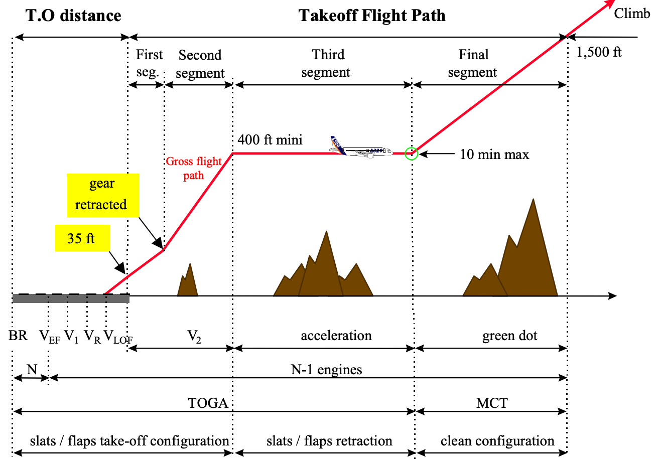
The takeoff in a transport category aircraft is divided into four segments. They are named, the 1st segment, 2nd segment, 3rd segment, and Final segment. The takeoff segments are always presented with one engine inoperative.
The 1st segment starts from VLOF to the point where the landing gear is retracted. In this segment, the aircraft speed is VLOF, the flaps are in takeoff configuration, and the engines must be at takeoff power. For a twin-engine aircraft, the climb gradient at this segment must be positive, and for a four-engine aircraft, it must be at least 0.5%.
The 2nd segment starts from the gear retraction point to an altitude of 400 ft AGL. The speed of the aircraft is V2. The flaps are still in takeoff configuration, and the engines are at takeoff power. The climb gradient for a twin-engine aircraft is 2.4%, and that for a four-engine aircraft is 3.0%.
The 3rd segment begins at 400 ft AGL. This is also known as the minimum acceleration height. At this segment, the aircraft's nose can be lowered and accelerated to flap retraction initiation speed to retract the flaps. Once flaps are retracted, the speed can be increased to minimum drag speed. The engines remain at takeoff power. There is no specific climb gradient requirement at this segment.
The Final segment begins once the aircraft is clean (flaps up). At this segment, the minimum drag speed is reached, and the engine power is pulled to MCT (Maximum Continuous Thrust). The final segment climb gradient for a twin is 1.2%, and that for a four-engine is 1.7%. The takeoff segments end once the aircraft reaches 1,500 ft AGL, at which point the climb phase begins.

