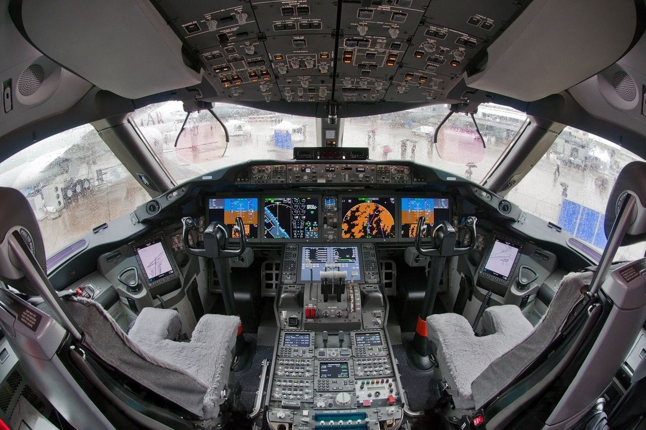
In this last part of the flight control series, we are going to look at the fly-by-wire flight control system.
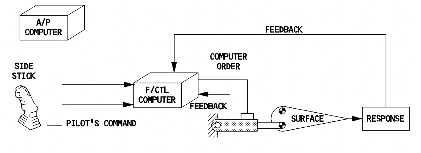
In a fly-by-wire control system, the pilot inputs on the control column or stick are picked up by sensors. These sensors send this data or information to a flight control computer which processes and refines it. Once processed, the computers command the appropriate flight control hydraulic actuators to move to maneuver the aircraft.
The fly-by-wire architecture
The heart of any fly-by-wire system is its flight control computers. It is the logic written into these computers which decides the behavior of the aircraft. This logic is known as a control law.
In its simplest form, a fly-by-wire control system consists of three parts. One is the sensors that convert the physical pilot control movements into data; the second is the flight control computers that process the data received by the sensors; and third, we have the flight control actuators.
Most fly-by-wire systems are closed-loop systems. This means that the flight controls give feedback to the computers about their movement and the control computers continuously send corrective data to the actuators to closely match the pilot's demands.
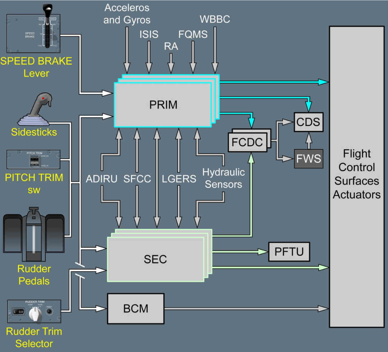
To make the computations easier and more accurate, flight control computers are fed a lot of information from aircraft systems. The following is a list of data that is sent to the flight control computers:
- Pilot inputs: The pilot inputs are the most important set of data the flight control computers need, as it is this that determines how the aircraft is to be maneuvered.
- Inertial and air data: The inertial data comes from the Inertial Reference System (IRS). Some of the IR data includes aircraft heading, roll, pitch, yaw, etc. The air data information comes from the Air Data Computers (ADC). These data include calibrated airspeed, angle of attack, altitude, etc.
- Accelerometers and gyrometers: The accelerometers and gyrometers are placed at various points on the aircraft. Accelerometers measure the aircraft's vertical and lateral acceleration, while the gyrometers measure the roll rate, pitch rate, and yaw rate. These data are highly important for flight control computers.
- Radio altimeters: In many fly-by-wire aircraft, the flight control laws require to be tweaked at different phases of the flight. For instance, when coming in for a landing, the control law might have to be modified to allow the pilot to have better control of the aircraft. To determine that the aircraft is coming into land, the flight control computers use the aircraft height data from the radio altimeters.
- Landing gear control system: This system feeds the flight control computers information about the position of the landing gear and whether the oleos are compressed or extended. The latter is used to determine if the aircraft is airborne or on the ground. For instance, the ground spoilers on the wings can only come up when the gear oleos are compressed. Hence, the flight control computers need this data before commanding the spoilers up.
The control laws
As discussed earlier, the control laws are what govern how the flight control computers command the flight control actuators. In most fly-by-wire control systems, there are three control laws. The naming convention of these laws varies from manufacturer to manufacturer, but they work similarly. The three control laws are:
- Normal law.
- Alternate law.
- Direct law.
The normal law is active when no system failures exist. When in normal law, the flight control computers work at their full capacity. On the other hand, the alternate and direct laws are reconfiguration laws that become active when system failures exist to the point where the computers can no longer compute accurate data for the control surface actuators.
Normal law
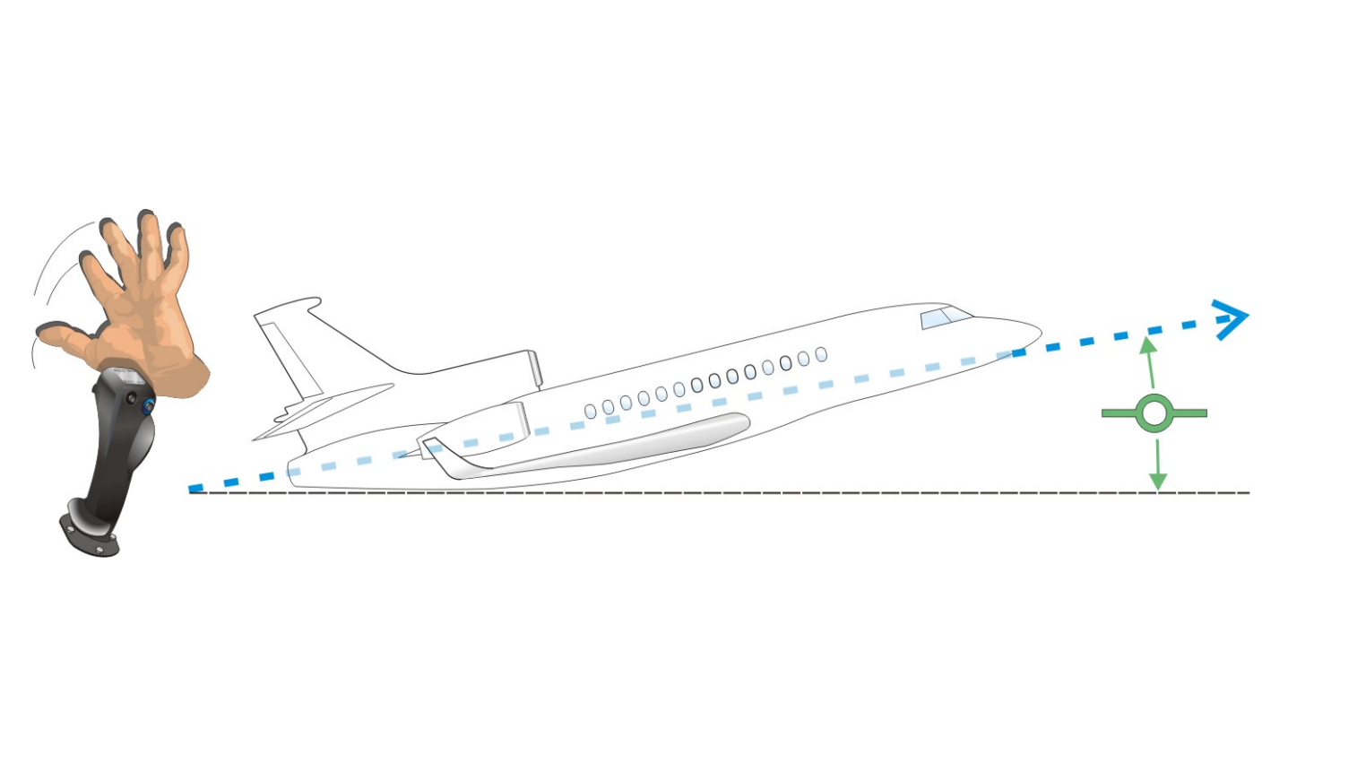
In a typical fly-by-wire aircraft, the control for pitch is a load factor demand. As the pilot moves his or her controls back and forward, the movement is converted to a g-load. This load is then sent to the flight control computers, which activate the control surfaces to meet the load factor demand.
For example, if a pilot pulls back on the controls, to increase the load factor by +0.5 gs while the aircraft is in +1.0 g unaccelerated flight, the flight control computers deflect the elevator controls to increase the aircraft load factor to +1.5 gs. And once the pilot lets go of the control column or stick, the aircraft is reverted to +1.0 g flight which puts the aircraft in a constant climb angle.
This is known as stick-free, zero-flight path variation flight. All the pilots must do is command a maneuver from the flight control column and let go of it once the desired command is given. The aircraft can maintain this flight path until the pilot commands a new flight path. The flight control trimming is also done automatically.
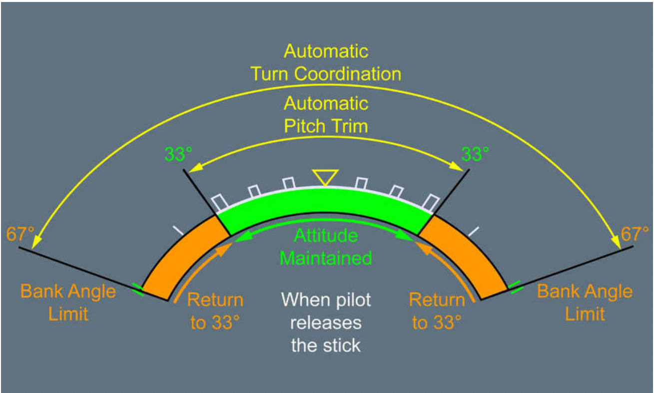
The roll control is a roll rate demand. That is, when the stick is moved sideways, the pilot movements are converted to a roll rate. The more the stick is deflected, the higher the roll rate becomes. The roll can also be made stick-free.
The yaw is usually a sideslip demand. When the rudder pedals are deflected, the computers receive a proportional sideslip demand.
Alternate and direct law
The alternate and direct law are degraded control laws that become active when aircraft system failures start to occur. The alternate law is the first level of control degradation. This can occur, for instance, when there is a major hydraulic failure that deactivates a number of flight control surfaces. With limited control surfaces, the flight control computer demands of normal law might not work on the aircraft.
When there are multiple failures, the aircraft reverts to direct law. An example can be the loss of inertial and air data information. In this situation, the loss of these data may prevent the flight control computers from making the required calculations for normal or alternate law. When in direct law, the computers just act as a medium to direct the control surfaces as the pilot demands. There is no refining of pilot input data.
When in alternate and direct law, most fly-by-wire aircraft become very sensitive in all control axes. Thus, they become very hands-on.
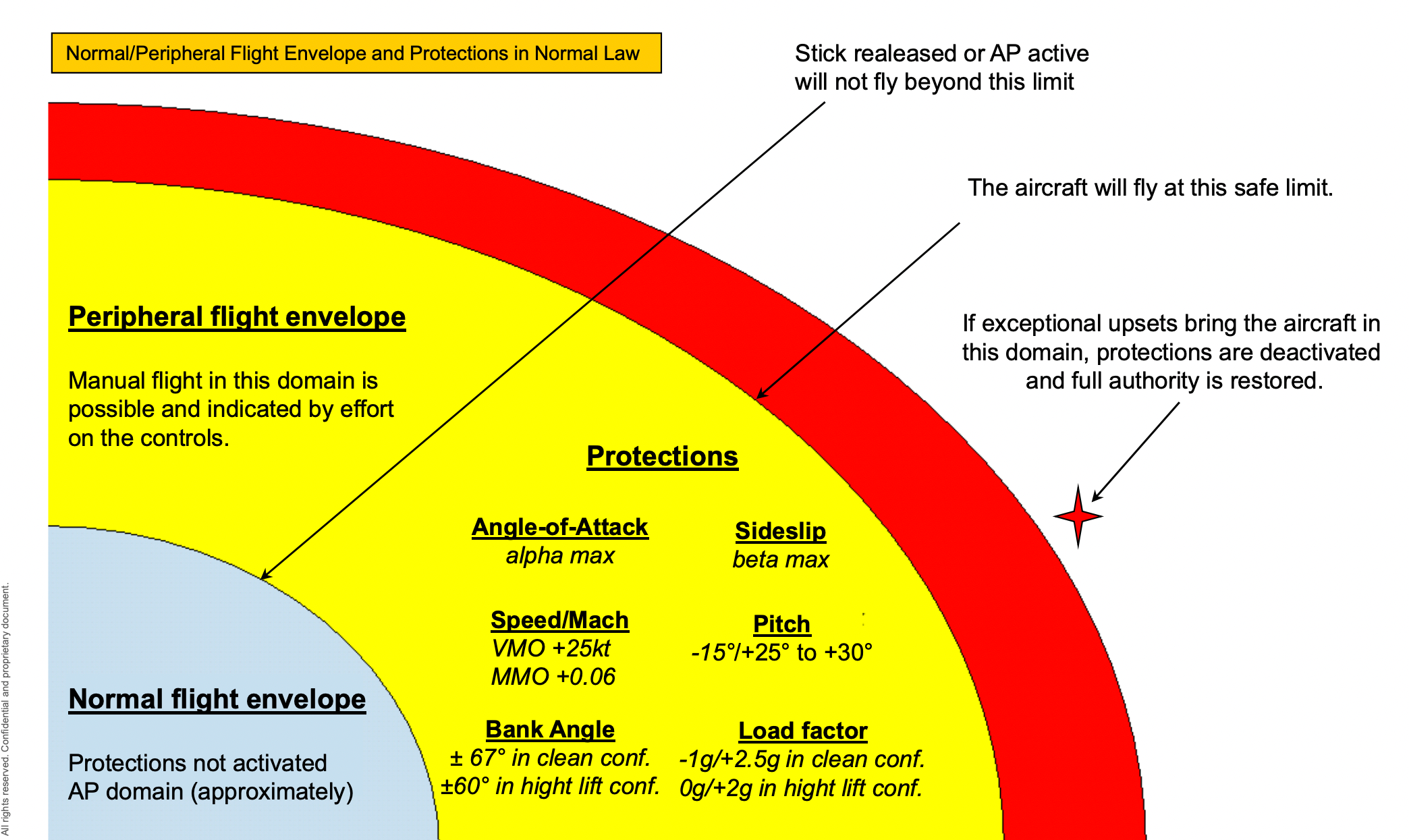
Flight envelope protection
The fly-by-wire system can provide flight envelope protection. That is, it can always keep the aircraft in its safe envelope. The protections are available in normal law and not in alternate and direct law. The common protections the fly-by-wire control systems offer is:
- High and low pitch protection.
- High angle of attack and stall protection.
- Overspeed protection.
- Load factor protection.
When the protections are active, the flight control computers limit the maneuvering of the aircraft when it reaches the limited parameters. So, even if the pilot gives full stick or control column deflection, the computers prevent the aircraft from exceeding any parameters beyond the protected limits.
But is it safe to give only a limited amount of control to the pilot? The answer to that question is that the protections activate only at the very edge of the flight envelope. For instance, in the Airbus aircraft, the load factor is limited by the flight control computers to +2.5gs. If you have a look at the aircraft limitations in the flight manual, you will see that exceeding +2.5gs could damage the aircraft structure. This is the maximum positive pitch allowable. So, the protections, even though limiting the control authority, become active only very close to the flight envelope.
The computers are also smart enough to understand if they can no longer provide protection or control. In this case, they downgrade the control system and deactivate the protections. They can also degrade the controls if the aircraft parameters are exceeded beyond a certain limit by an external factor such as wake turbulence. This degradation gives the pilot full control authority to get the aircraft out of the situation.
In some fly-by-wire aircraft, the protections are soft in that they could be exceeded if the pilot applies enough force on the controls. This is the Boeing concept of envelope protection.
Fly-by-wire redundancies
One of the biggest disadvantages of a fly-by-wire control system is that if a flight control computer fails, there is a chance of loss of control. To prevent this from happening, all fly-by-wire aircraft are provided with backup flight control computers. If one fails, the other takes over.
In older fly-by-wire aircraft, some manual form of control is provided. For example, in the Airbus A320, the rudder and trimmable horizontal stabilizer have manual controls. Thus, even if all the flight control computers fail, the aircraft can be somewhat controlled by the pilot.
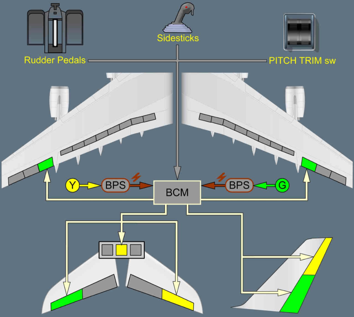
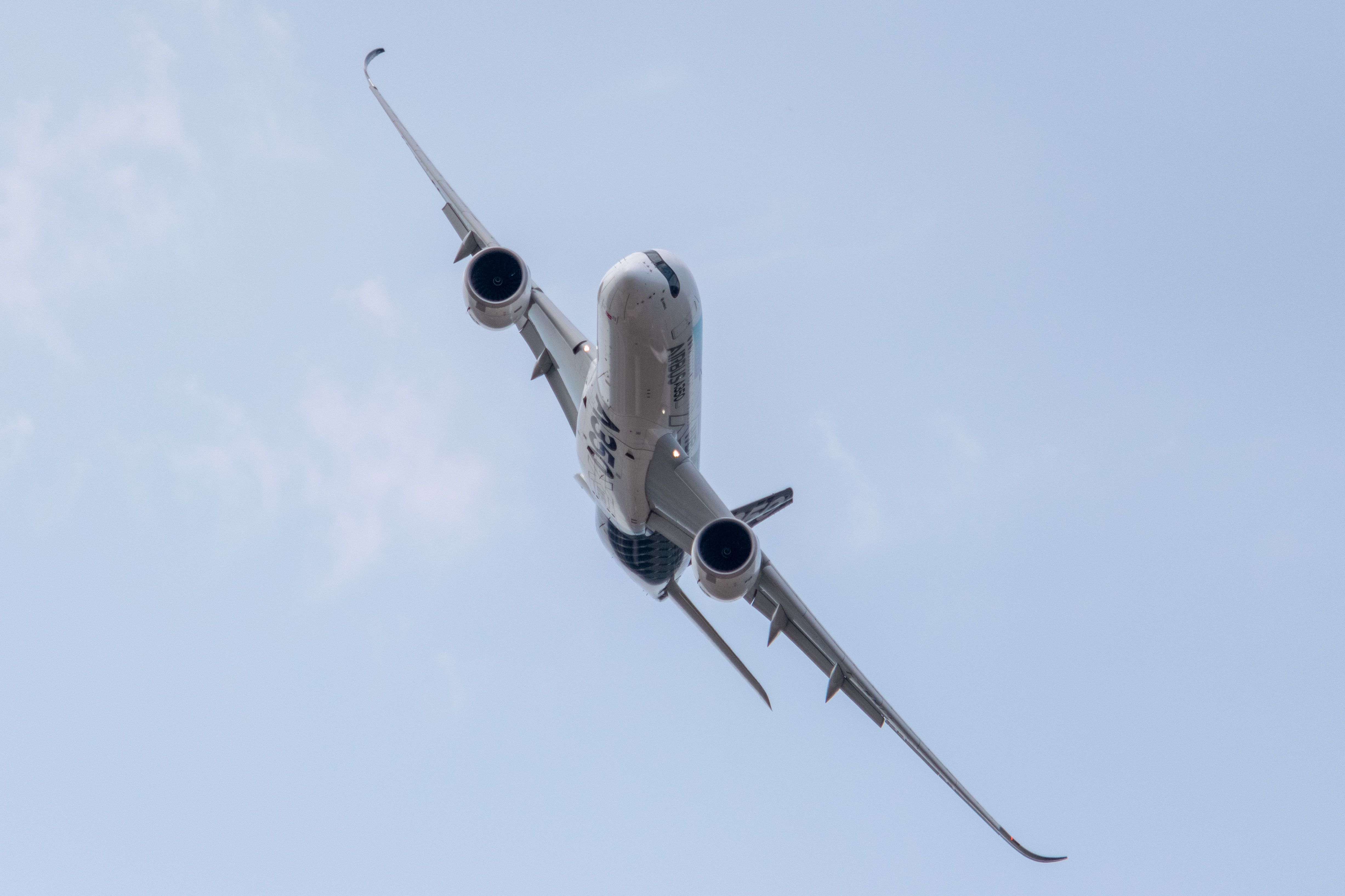
In newer fly-by-wire aircraft, there are zero mechanical controls. However, these aircraft are provided with multiple redundancies. The Airbus A380 and A350 have a Backup Control Module (BCM), which has a generator of its own. If all the flight control computers fail, the BCM can give rudimentary control of the aircraft to the pilot. The BCM is powered by one of the hydraulic systems of the aircraft.

.jpeg)
